Sign In | Join Free | My himfr.com
Home > Carbon Film Resistor >

1/4 Watt Carbon Film Resistors - Through Hole

Jackcon (HK) Industrial Limited
Contact Now
    Buy cheap 1/4 Watt Carbon Film Resistors - Through Hole from wholesalers
     
    Buy cheap 1/4 Watt Carbon Film Resistors - Through Hole from wholesalers
    • Buy cheap 1/4 Watt Carbon Film Resistors - Through Hole from wholesalers

    1/4 Watt Carbon Film Resistors - Through Hole

    Ask Lasest Price
    Brand Name : JK
    Certification : ROHS
    Model Number : CFR1/4W
    Price : Negotiable
    Delivery Time : 3-7 working days
    Payment Terms : T/T & Paypal
    Supply Ability : 200,000,000,000Pcs per month
    • Product Details
    • Company Profile

    1/4 Watt Carbon Film Resistors - Through Hole

    Quick Details


    Carbon film resistors are a significant improvement on carbon composition. However, in comparison to metal film and metal oxide film, the commercially available range steadily decreases. Metal and oxide film are not more expensive to produce, and have overall better properties.


    Description:


    Carbon film resistors are a fixed form type resistor. They are constructed out of a ceramic carrier with a thin pure carbon film around it, that functions as resistive material.

    Application


    Typical use for carbon film resistors is in high voltage and temperature applications. Operating temperatures are up to 15kV with a nominal temperature of 350°C. Examples are high voltage power supplies, radar, x-rays and laser.

    Specification


    Structure diagram

    The construction of resistor (CFR series) shall be as follows:
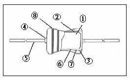
    NO

    Item

    Material

    1

    Ceramic core

    High alumina ceramic is used.

    2

    Resistor element

    The resistor element shall consist of carbon film.

    3

    Terminal

    Tinned iron cap.

    4

    Connection

    The lead wire, which is plated with solder, shall be mounted to the caps by welding process.

    5

    Lead wire

    Soldered or tinned annealed wire.

    6

    Undercoat painting

    Electric insulation resin.

    7

    Finishing painting

    Epoxy resin is used.

    8

    Indication

    Color code.


    1.Electrical Ratings


    STYLE

    MAX

    WORKING

    MAX

    OVERLOAD

    RESISTANCE

    VALUE RANGE

    CF1/6W / CF1/8W

    200V

    400V

    0.1Ω〜22MΩ

    CF1/4W / CF1/4WS

    300V

    600V

    0.1Ω〜22MΩ

    CF1/2W / CF1/2WS

    350V

    700V

    0.1Ω〜22MΩ

    CF1W / CF1WS

    500V

    1000V

    0.1Ω〜22MΩ

    CF2W / CF2WS

    500V

    1000V

    0.1Ω〜22MΩ

    CF3W / CF3WS

    600V

    1000V

    0.1Ω〜22MΩ

    CF5W / CF5WS

    600V

    1000V

    0.1Ω〜22MΩ

    2. Reliable test


    ITEM (STANDARD)

    PERFORMANCE AND/OR

    QUALIITY ACCEPTANCE

    TEST METHOD

    Resistance value Vs

    Temperature

    Characteristics

    For RX∠100KΩ

    +350〜-500PPM/℃

    100KΩ≦RX ≦1MΩ

    0〜-700PPM/℃

    1 MΩ ∠ RX

    0〜-1500PPM/℃

    JIS-C-5202 5.2

    Measure resistance (Ro ohm) at room

    Temperature(To ℃)

    Measure again the same at 100℃

    Higher than room temperature

    6

    R – RO 10

    PPM = *

    RO (T0+100) –T0

    Short time overload

    The resistance variation shall be

    within±(0.75% + 0.05 ohm) and there

    Shall be no mechanical breakage

    JIS-C-5202 5.5

    Apply DC voltage 2.5times the rated

    Voltage for 5 seconds

    The leave at room temperature for 30

    Minutes then measure MAX overload

    Voltage 0.50W – 700V (DC)

    Insulation resistance

    1000M ohm or more

    JIS-C-5202 5.6 In V-BLOCK

    Lay the resistor on 90° angle metal V

    Block apply 100VDC between resistor

    Lead and V block for one Minute And

    Measure

    Voltage endurance

    The resistance variation shall be

    within±(2% + 0.05ohm) and there

    shall be no mechanical breakage

    JIS-C-5202 5.7

    Icy the resistor on the 90° angle metal V

    Block and apply reamed AC voltage for

    One Minute. Test voltage 0.25W –

    500V (AC) 0.50W –700V(AC)

    Intermittent overload

    Resistance variation shall be

    Within ±(2.00% + 0.05ohm)

    JIS-C-5202 5.8

    Apply AC voltage 4 times the rated

    voltage for 1 second and rest for 25

    seconds and Repeat this cycle for

    10000±200times leave resistor 30

    minutes at room temperature after test

    and measure Maximum voltage for

    intermittent Overload.0.50W-700V(AC)

    Terminal strength

    Resistance variation shall be within

    ±(0.5% + 0.05ohm) also there

    Shall be on mechanical breakage

    Pull test: apply 2.5kg force to the

    lead in the direction of lead

    axislor30±5 seconds.

    Heat resistively

    Against soldering

    Resistance variation shall be within ±

    (1.0%+0.05ohm) also there

    Shall be on mechanical breakage

    JIS-C-5202 7.10

    Dip the lead in to a solder bath having a

    Temperature of 350℃ ± 10℃ up to

    4±0.8mm from the body of the resistor

    at room temperature 3 hours after ,then

    Measure

    Solder ability

    More than 95% of the surface of the

    lead shall be covered by new solder

    after the leads are dipped in the

    Solder

    JIS-C-5202 6.5

    Dip the lead in to a solder bath having a

    Temperature of 260℃± 5℃ up to

    4±0.8mm from the body of the resistor and

    hold it for 5 ± 0.5seconds then inspect

    Humidity load test

    Resistance variation be

    Within ± (3.0% + 0.05ohm)

    Also there shall be mo mechanical

    breakage

    JIS-C-5202 7.9

    In temperature chamber having

    temperature 40℃± 2℃,relative

    humidity 90 – 95%, Apply rated

    voltage 1.5hour and shut voltage 0.5

    hour repeat this cycle for 1000 hours,

    leave in room temperature for lhour

    after test, then measure

    Load life test

    The variation of the resistance

    Shall be within ± (3%+0.05ohm)

    Also there shall be no mechanical

    Breakage

    JIS-C-5202 7.10

    In the constant temperature chamber having

    Temperature70℃ ± 2℃,apply rated

    Dc voltage for 1.5hour and shut voltage for

    0.5 hour and repeat thin cycle for 1000

    hours, leave in room temperature lhour

    after test, then measure


    3.Color refer


    Color

    1 st Band

    2 nd Band

    3 rd Band

    4 th Band

    Black

    0

    0

    0

    10


    Brown

    1

    1

    1

    10


    Red

    2

    2

    2

    10

    ±2.0%

    Orange

    3

    3

    3

    10


    Yellow

    4

    4

    4

    10


    Green

    5

    5

    5

    10


    Blue

    6

    6

    6

    10


    Violet

    7

    7

    7

    10


    Grey

    8

    8

    8

    10


    White

    9

    9

    9

    10


    Gold


    -1

    10

    ±5.0%

    Silver


    -2

    10

    ±10.0%


    4. External dimensions

    P type


    Type

    Dimensions

    Normal Size

    Small Size

    I±2.0

    L±1.0

    ψD

    ψd±0.05

    H±2.0

    CF1/8W

    CF1/4WS

    60

    3.2

    1.8±0.5

    0.43

    28

    CF1/4W

    CF1/2WS

    60

    6.5

    2.3±0.5

    0.45

    28

    CF1/2W

    CF1WS

    60

    9.0

    3.2±0.5

    0.50

    28

    CF1W

    CF2WS

    60

    11.5

    4.5±1.0

    Quality 1/4 Watt Carbon Film Resistors - Through Hole for sale
    Inquiry Cart 0
    Send your message to this supplier
     
    *From:
    *To: Jackcon (HK) Industrial Limited
    *Subject:
    *Message:
    Characters Remaining: (0/3000)